Wednesday 16 December 2015

Designing a badge for Kiwicon in PCBmodE

Recently i decided to try my hand at designing a PCB using PCBmodE - a PCB EDA which takes a different design tact from traditional EDAs such as Kicad and Eagle.
The key difference between PCBmodE and a traditional EDA is the ability to create patterns on the board in the different layers of the PCB using common graphics design tools. This allows for a greater amount of creativity in the layout phase of a design - at the expense of design rules that normal EDAs place to prevent you from doing the wrong thing.
PCBmodE is the creation of Dr. Saar Drimer from Boldport - an Electronics Craftmanship company which turns out some amazingly pretty and functional PCBs for a variety of clients.


So why did i not just use Kicad/Eagle/something else? Because i wanted to see what you can create using alternative tools and methodology from a regular board - and for the kicks.
First step was to design a circuit - for the project in mind i wanted something basic and obnoxious - so flashing LEDs it was.
Initially i was thinking of designing something with a basic clock and shifters - then came to my senses when i realised its cheaper now to buy a microcontroller then all the parts needed for an old 80's design.
I'd recently just come back from Defcon in the US and had lucky enough to get one of the badges DC503 made for their party ( designed by @securelyfitz ) which used the Atmel ATTINY85.
So i decided to rip their circuit off for this badge (sorry guys/girls)!

The Schematic

So i sat down and created a simple LED flasher circuit using charlieplexing to maximise the number of LEDs i could flash (again - wanting to annoying the maximum amount of people).
This uses a ATTINY85, a 5050 LED, a bunch of 1206 LEDs, 0805 resistors, a push button switch and a CR2032 coin cell battery
I ordered most of the components of Alibaba - my favourite place to buy components as it is cheap as chips - but slow, so slow.

Board Design

Next i had to design the board.
First step was to read the documentation and look at some of the example boards.
It took a while to grok how to design boards in PCBmodE.
Here's how i did it:

Step 1 - Creation of Component Footprints

Create the component footprints in the ./components directory. I took the components json's given in the hello-solder project and then altered these to suit each component. The idea here was to get the components correctly defined before trying to get creative.

Step 2  - Placement of components

Place a few components in the ducksec-badge.json file to provide an idea of how it works.
Again here i took the hello-solder.json and stripped it down to suit my needs.

Step 3 - Generate the SVG file

To generate the SVG from our test ducksec-badge.json we use the following command
python ../pcbmode.py -b ducksec-badge -m 
from the ./cool-pcbs directory of PCBmodE

This generates an SVG file that i then open in Inkscape.

Step 4 - Creating the board outline

To form the shape of the board you edit the "outline" layer. Now this is not copied back to the JSON when you start editing so you have to copy the
Shift-Ctrl-X gives you the XML description of the SVG.
So you select the outline layer
Click the unlock icon
Select the svg:path
Then copy the "d" values printed.

You then open the kiwicon-badge.json
Goto the "outline" tag
and insert the copied "d" values into the "value" string.
"outline": {
 "shape": {
  "type": "path",
  "value": "m 7.614166,...,-32.7480675 z",
  "location": [
   -0.1268844, -2.257778
   ]
 }

},
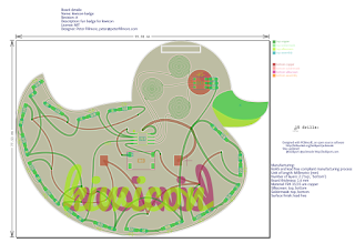
Regenerate the board using the above PCBmodE command and you should see the shape you designed in Inkscape - here a nice rubber ducky.


Step 5 - Placing your components

Now you should be able to place your components on the board.
Here I created all the different components in the kiwicon-badge schematic and incremented the locations so they were spread around the generated SVG and I could clearly see them. 
"D1": {
 "footprint": "1206-LED",
 "layer": "top",
 "location": [
 -6.9479856,
 11.8223
 ],},
I then regenerated the SVG and start placing the components in the areas i want them on the board. To do this i lock all other layers and unlock the "assembly", "solderpaste", "soldermask", "silkscreen", "pads" and "drills" layers. Then select the whole component and place this where i want it.
After placing the components i can then regenerate the JSON file from my edited SVG using the following command:

python ../pcbmode.py -b kiwicon-badge -e
This extracts your changes from the SVG and creates a JSON with them imbedded. Now this only works for certain layers - so you can't do this with the outline.

Step 6 - Routing

Generate the SVG again with the changes you've made to date
python ../pcbmode.py -b kiwicon-badge -m

Select the "copper" folder and the "routing" layer.
Then start connecting the components together with curves in the SVG program. Take special care to not cross traces on a layer.

To add a via you draw a dot, then redefine that dot as a via in the XML of the SVG.

Take care in this step to slowly and methodically join the circuit together to match your schematic as you don't have a netlist to guide you.

Step 7 - Repeat steps 5 and 6

Iterate over steps 5 to 6 to design the board. Be artistic - this is why you are using PCBmodE!


Step 8 - Generate your gerbers/manufacturing files.

So at this point you should be happy with the design you've made and almost ready for sending to your chosen board house.
To generate the gerber files:

python ../pcbmode.py -b kiwicon-badge --fab "dirtypcb"

The "--fab" argument allows you to set the files naming that a board manufacturer wants. In this case i used DirtyPCB; but you can adapt the pcbmode_config.json to suit the board house of your choice.

You can then review the generated gerbers using a gerber viewer to ensure that it looks correct on for each layer (personally i use gerbview included in the kicad package).

After

At this point i thought it looked good - so sent the board for printing.
I like dirtypcb as the shipping is cheap and quality is a lot higher then what they describe on the site.

A few weeks later i receive my boards and components needed. At this stage it was <1 week to kiwicon so i had to hope i hadn't mucked up and the circuit was good.

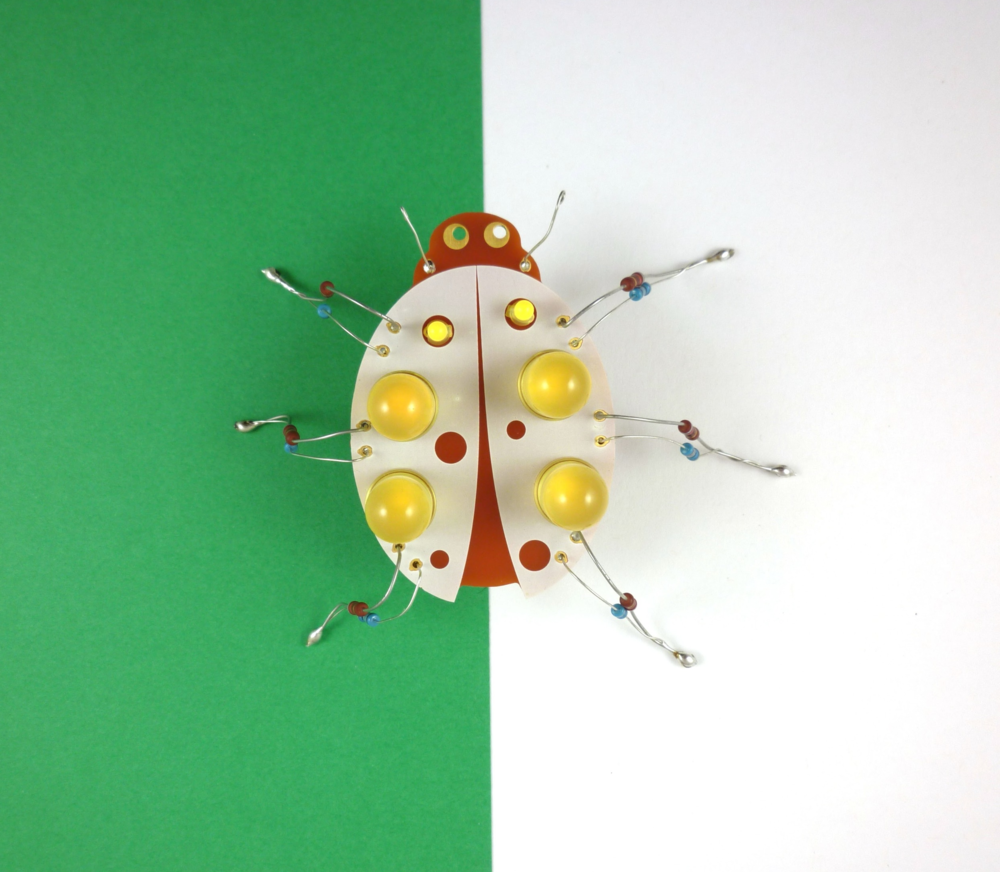
I threw one together in an hour or so and to my surprise all the parts worked;
except i had wired to the switch to the reset pin of the processor :(
And wired the switch closed :(
But easy to fix with a few bodge wires :)

Next i had to write some code - quick search got me a good avr-template and i was ready to roll.

So how did it look:

Code:

Source at

https://github.com/peterfillmore/kiwicon_badge

PCB at:

https://github.com/peterfillmore/kiwicon_badge/pcb

Things I broke in the rush

  • Wired the switch to the reset pin of the microcontroller.
  • Wired the switch closed.
  • Didn't calculate idea resistors/currents for each LED (just threw them on the board and hoped)
  • Burnt a few LEDs in assembly
  • Disabled reset on a few ATTINYs and caused the chip to lose in circuit programming mode.
  • Couldn't get interrupt on a remapped reset pin to work on the ATTINY
Other then that - it worked great.


Monday 25 May 2015

Enabling an additional screen in a Qubes OS Windows HVM

Enabling an additional screen in a Qubes OS Windows HVM

I recently converted my work laptop over to using Qubes OS; an awesome OS based around the concept of using lightweight VMs to provide enhanced security.
Naturally I added a Windows VM using this handy guide http://www.qubes-os.org/doc/WindowsAppVms/ to install and configure a working Windows 7 install so i could run Powerpoint.
Everything worked great until i connected an external monitor; naturally my Qubes desktop expanded to fill the new monitor but my Windows VM was still stuck with a single display window. This is great but i needed a second window so i could view my presentation notes when doing a talk using the built in view in Powerpoint.
At first I thought maybe I could enable this through the ".conf" file for VM but couldn't find any option to enable emulation of an additional screen.
I tried assigning the video adapter hardware to the running VM but all that did was disable my laptop screen.
However I had success configuring it directly in the Windows VM.

Instructions 

  1. Connect up your external monitor to your system - Dom0 should detect and extend your desktop to this display.
  2. Boot your Windows VM and open the device hardware pane. 
  3. Enable The "Standard VGA Graphics Adapter" and reboot the VM.
  4. Test that Powerpoint now detects your screen.
  5. Resize the new window through windows to make it usable
Now you should be able to read your presentation notes while talking!
I highly recommend you give Qubes a go as it's a great idea with lots of advantages when you need to run lots of different applications and OS's on a single computer.


Tuesday 14 May 2013

Coordinated ATM Heists, and a rant...

Been a while since I posted, have been a bit flat out with lots of multiple projects on different continents.

This story is a great one for those of us in the payments security field.
http://krebsonsecurity.com/2013/02/crooks-net-millions-in-coordinated-atm-heists/
http://www.theverge.com/2013/5/13/4326336/cyber-caper-behind-the-scenes-of-the-45-million-atm-heist
http://www.reuters.com/article/2013/05/13/us-usa-crime-cybercrime-electracard-idUSBRE94C0K220130513

This is an interesting story in that it was not the card-holder data that was attacked, but the balance and withdrawal limits data that was breached. There is a chance that the payment processors were PCI compliant as these standards are concerned with the protection of card-holder data, not with balances on accounts or withdrawal limits.

This is a good lesson to all payment processors that PCI compliance alone is not sufficient security. You must continually assess and test your payment environment for security vulnerabilities.

Also, countries not using chip-card/EMV should hurry up and join the rest of the world.


Magstripe is a broken technology, it contributed to the above attack (the pre-paid cards were cloned allowing an exponential increase in the losses occured).
EMV/Chip Cards cannot be economically cloned, which reduces the economic impact of attacks like the one above.


Why is a product like this: https://squareup.com/stand even feasible in 2013? Almost all payment terminals produced now support Chip/EMV transactions.
$299 for a product that is not PCI compliant, already obsolete and insecure; sounds like the Windows 3.1 of payment terminals...

Wednesday 13 March 2013

Nice write-up on issues in TLS/SSL

Haven't blogged in a while due to studying for the CISSP certification and working on other fun projects. Amazon EC2 instances are enormous fun to play with, and free to get started with, wish i had this type of stuff when i was in uni.

Came across this great story on RC4 and TLS:
Attack of the week: RC4 is kind of broken in TLS
Cipher suites in the TLS/SSL implementations have been an interesting area of late with a number of attacks being published in the last few months.
A fun thing to do is to scan a website using the TLSSLED shell script and see what cipher suites it supports.
Here's the output for google.com:

         Accepted  SSLv3  256 bits  ECDHE-RSA-AES256-SHA
    Accepted  SSLv3  256 bits  AES256-SHA
    Accepted  SSLv3  168 bits  ECDHE-RSA-DES-CBC3-SHA
    Accepted  SSLv3  168 bits  DES-CBC3-SHA
    Accepted  SSLv3  128 bits  ECDHE-RSA-AES128-SHA
    Accepted  SSLv3  128 bits  AES128-SHA
    Accepted  SSLv3  128 bits  ECDHE-RSA-RC4-SHA
    Accepted  SSLv3  128 bits  RC4-SHA
    Accepted  SSLv3  128 bits  RC4-MD5
    Accepted  TLSv1  256 bits  ECDHE-RSA-AES256-SHA
    Accepted  TLSv1  256 bits  AES256-SHA
    Accepted  TLSv1  168 bits  ECDHE-RSA-DES-CBC3-SHA
    Accepted  TLSv1  168 bits  DES-CBC3-SHA
    Accepted  TLSv1  128 bits  ECDHE-RSA-AES128-SHA
    Accepted  TLSv1  128 bits  AES128-SHA
    Accepted  TLSv1  128 bits  ECDHE-RSA-RC4-SHA
    Accepted  TLSv1  128 bits  RC4-SHA
    Accepted  TLSv1  128 bits  RC4-MD5

The interesting listing in this case is "RC4-MD5", considering the MD5 is considered broken and should have been retired by now. 

Compared this to api.square.com:443:

    Accepted  SSLv3  256 bits  AES256-SHA
    Accepted  SSLv3  168 bits  DES-CBC3-SHA
    Accepted  SSLv3  128 bits  AES128-SHA
    Accepted  SSLv3  128 bits  RC4-SHA
    Accepted  TLSv1  256 bits  AES256-SHA
    Accepted  TLSv1  168 bits  DES-CBC3-SHA
    Accepted  TLSv1  128 bits  AES128-SHA
    Accepted  TLSv1  128 bits  RC4-SHA
Which is in line with FIPS 140-2 Annex A.


Monday 11 February 2013

Nice attack on an bad implementation of using the Atmel SAM7XC Crypto Co-Processor

http://oamajormal.blogspot.co.uk/2013/02/atmel-sam7xc-crypto-co-processor-key.html

This is why hardware key management is so important. In this case the processor contains hardware cryptographic engines yet no dedicated key storage or tamper protection. This means that keys have to be stored in internal Flash or RAM which opens up vulnerabilities allowing keys to be extracted.

A proper secure processor implements dedicated key storage memory combined with active tamper detection. If a tamper event is detected by the processors security sub-system; then the key storage area will be actively cleared preventing key extraction. Examples of these processors include the Maxim USIP, Freescale i.MX258 or the Broadcom BCM5982.

The analysis performed here validates how much implementation matters when designing a secure system.


Monday 4 February 2013

iOS 6.x Untethered Jailbreak out

Available at: http://evasi0n.com/

I recommend checking the SHA-1 hash of the release you downloaded against the provided list (a habit I should get into as well). This can be performed by using OpenSSL:
openssl sha1 <filename>

Interesting that the jailbreak steps are different from the "redsn0w" utility, not having to get the device into DFU mode is great as I muck it up every time and have to reboot.
The installer places a "Jailbreak" icon onto the SpringBoard as part of the process which has to be clicked, i'm interested to know what role this performs in the jailbreak process.

Make sure if you've jailbroken your device to change the your default root password to something you've chosen! we don't want this happening again.

ssh root@<ip of your device>
iPhone:~ root# passwd

Changing password for root.
New password:

and heres a great writeup of what the jailbreak does:
http://blog.accuvantlabs.com/blog/bthomas/evasi0n-jailbreaks-userland-component

Friday 1 February 2013

Hooking objective-c internals using the Captain Hook framework.

One of the fun things to do with a Jailbroken iPhone is to install custom themes using the "WinterBoard" application.
This allows you to install themes such as: Auxo which customises the application switcher bar or Boss.ios which alters the whole look of the interface.

How does "Winterboard" work?

The "WinterBoard" application works by "hooking" the existing internal classes using the Objective-C Runtime Library. This library is loaded by all Objective-C applications to support the dynamic features of the language which means that we can utlilise is to perform our own alterations to the OS and applications.
This allows for the alteration of icons, sounds and textures without having to touch the originals supplied with the device. This means that you can alter the device without the risk of breaking the device.

The CaptainHook framework

This is a header file created by Ryan Petrich(http://rpetri.ch/) to assist with the creation of hooking libraries using the Objective-C runtime. This provides a functions to assist in the setting up of custom hooking code. Documentation is a little scant so hopefully this blog can help you begin to create your own hooks.

Getting started

I've altered the sample code provided at the Github as the function used has been depreciated by Apple
hook source code and a makefile
#import <CaptainHook/CaptainHook.h>
CHDeclareClass(NSString); //set up the Captain Hook Library

//function called when hook is encountered
CHMethod(4, void, NSString, writeToFile, NSString *, path,  
         atomically, BOOL, useAuxiliaryFile, encoding,  
         NSStringEncoding, end, error, NSError **, error) 
{
  NSLog(@"Writing string to %@: %@", path, self);
  //send received arguments to the original class
  CHSuper(4, NSString, writeToFile, path, atomically,
  useAuxiliaryFile, encoding, end, error, error);
}

//create the hook
CHConstructor
{
  CHLoadClass(NSString); //setup the class
  //hook the chosen method
  CHHook(4, NSString, writeToFile, atomically, encoding, 
  error);
}

Heres a sample program you can test it with:
link to test program and makefile
#import <Foundation/Foundation.h>
#import <Foundation/NSString.h>

int main(void) {
  NSAutoreleasePool *pool = \
    [[NSAutoreleasePool alloc] init];
  NSString *testString = @"Hello, I am the test string";
  [testString 
    writeToFile:@"test.txt" 
    atomically:YES 
    encoding:NSASCIIStringEncoding 
    error:NULL];
  [pool release];
  return 0;
}

Compiling

Compiling works on OS X with xCode 4.x and iOS SDK version 6.0 in the default library locations.
Copy the compiled "testhook" and "stringHook.dylib" to your device. SSH in, export DYLD_INSERT_LIBRARIES and then execute "testhook" e.g:
  desktop$ scp ./hooktest ./stringHook.dylib \
root@<device ip>:/var/root/
  desktop$ ssh root@<device ip>
  device # export \
DYLD_INSERT_LIBRARIES="/var/root/stringHook.dylib"
  device # /var/root/hooktest

And you should see:
  2013-02-01 21:40:58.710 hooktest[562:707] Writing string to   
  test.txt: Hello, I am the test string
Which only works for command line apps as export DYLD... does not get performed by SpringBoard


A bit of explanation

The CHMethod function declaration is:
  CHMethod(number of inputs, return type, class name, name1, type1, 
  arg1, name2, type2, arg2 ...(number of inputs));

An easy way to fill this method is to take the method definition, and fill it in left to right e.g.
  [NSString writeToFile: atomically: encoding: error:]
  -(BOOL)writeToFile:(NSString *)path atomically:   
  (BOOL)useAuxiliaryFile encoding:(NSStringEncoding)enc error   
  (NSError **)error
translates to:
  CHMethod(4, void, NSString, writeToFile, NSString *, path,    
  atomically, BOOL, useAuxiliaryFile, encoding, NSStringEncoding, 
end, error, NSError **, error)
We set the return type to void as for the example we don't return anything

The function declaration of CHSuper and CHHook are:
CHSuper(number of inputs, class name, name1, arg1, name2,
arg2 ...(number of inputs)

CHHook(number of inputs, class name,name1,name2,
...(num of inputs)


Other ways of inserting the injection library

Using launchctl seems to be a great way.
launchctl setenv DYLD_INSERT_LIBRARIES "/path/to/dylib"
which can be used for individual SpringBoard apps
or you can insert this plist key into one of the plists in "/System/Library/LaunchDaemons/"
although be careful! i screwed up my SpringBoard.plist editing it which caused the SpringBoard to stop loading(i.e no icons), so make a backup of the file just to be sure.
<key>EnvironmentVariables</key>
<dict>
<key>DYLD_FORCE_FLAT_NAMESPACE</key>
<string>1</string>
<key>DYLD_INSERT_LIBRARIES</key>
<string>/path/to/dylib</string>
</dict>

reload the plist using
launchctl unload <chosen plist>
then reload
launchctl load <chosen plist>

Another easy method is to install MobileSubstrate and copy the dylib to "/Library/MobileSubstrate/DynamicLibraries" and reload the SpringBoard. MobileSubstrate loads all the dylibs in this folder automatically.

Heres another piece of sample hooking code i created playing this stuff: https://github.com/peterfillmore/touchHook
This changes the status bar each time a touch is detected.

A great use of this hooking in security testing has been recently released by Jeremy Allen which uses it to disable certificate verification. http://intrepidusgroup.com/insight/2013/01/scorched-earth-how-to-really-disable-certificate-verification-on-ios/
So play around with it and see what fun you can have.